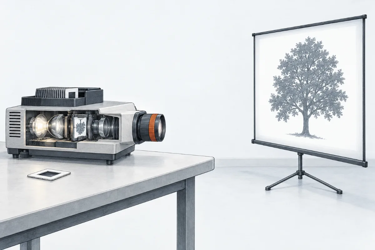
A slide projector stands on a table and throws a picture of a tree onto a screen across the room. The tree on the slide is smaller than a postage stamp, but the tree on the screen is as tall as a child. Carry the screen a step closer or a step further away, and the tree turns into a grey blur; only at one distance is it sharp. A camera does the opposite job: it makes a tiny picture of a whole street, and it too has to be focused. Both work with a lens. This part is about how a lens makes a sharp picture, and why the picture is sharp in only one place.
 (enlarge)
Two kinds of lens
A lens is a piece of glass or clear plastic with curved faces. Light is refracted where it enters the lens and again where it leaves, and because the faces are curved, rays passing through different parts of the lens are bent by different amounts.
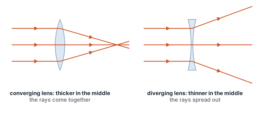
- A converging lens is thicker in the middle than at its edges. It bends rays of light towards each other. A parallel beam of light passing through it comes together at one point.
- A diverging lens is thinner in the middle than at its edges. It bends rays of light away from each other. A parallel beam passing through it spreads out, as if it came from a point on the side the light came from.
The lenses in this module are thin: they are thin compared with the distances to the objects and images. In a ray diagram, a thin lens is drawn as its outline with a straight line through the middle, and each ray is drawn bending once, at that line, instead of twice, at the two faces.
 (enlarge)
Trap: “The rays stop at the point where a converging lens brings them together.” Light carries on in straight lines. The rays cross at that point and spread out again beyond it, so a screen placed further away shows a blurred patch of light, not a point.
The principal focus and the focal length
To describe what a lens does, you need three terms.
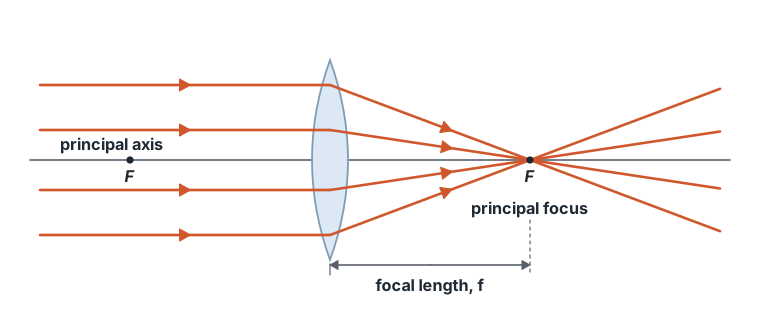
- The principal axis is the line through the centre of the lens at right angles (90°) to it.
- Rays parallel to the principal axis that pass through a converging lens are all refracted through one point on the axis: the principal focus, also called the focal point, F.
- The focal length, f, is the distance from the centre of the lens to the principal focus.
Light can pass through a lens in either direction, so a lens has a principal focus on each side, both at the same distance f from its centre. A lens with more strongly curved faces bends light more and has a shorter focal length.
Rays of light from a very distant object, such as a tree across a park seen through a window, are practically parallel when they reach the lens: rays from one point of the tree that reach a small lens are so nearly side by side that you cannot tell them from parallel. So a converging lens forms a sharp image of a distant object at its principal focus. That gives a simple way to measure the focal length: focus the image of a distant object on a screen and measure the distance from the lens to the screen. Never use the Sun for this: an image of the Sun at the focus is hot enough to burn, and looking at it can damage your eyes.
 (enlarge)
Trap: “The focal length is the distance from the lens to the image.” Only for a very distant object is the image at the principal focus. For a nearer object the sharp image is further from the lens than F, as you will measure on the bench.
Worked example
Finding the focal length
A pupil holds a converging lens by a classroom window and moves a white card behind it until a small, sharp, upside-down picture of a tree far outside appears on the card. The lens is at the 20.0 cm mark of a metre rule and the card is at the 34.5 cm mark. Find the focal length of the lens.
The tree is far away, so the rays from each point of it arrive at the lens practically parallel, and the lens brings them together at its principal focus. So the card, where the image is sharp, is at the principal focus, and the focal length is the distance from the lens to the card: 34.5 cm − 20.0 cm = 14.5 cm. The focal length of the lens is 14.5 cm.
On the optical bench
Now find the focal length of a lens, and then use the lens to make images of a lamp.
What is on the bench. An optical bench: a metre-long rail with a centimetre scale along its front. A converging lens, 5.0 cm across, stands in a holder at the 40 cm mark; its focal length is what you find first. A white card screen slides along the rail on the other side of the lens. At the far end of the room, behind the start of the bench, is a window, with trees a long way outside it. Beside the bench waits a lamp box with a hole cut in its front in the shape of an arrow, 2.0 cm tall; when the lamp is on, the bright arrow is the object. The foot of the arrow, the centre of the lens and the centre of the screen are all at the same height, on the principal axis.
What you do. Let in the window’s light, predict what the lens does to it, then slide the screen until the picture of the window is sharp: the distance from the lens is the focal length. Next, put the lamp on the bench 30 cm from the lens, predict what kind of image it will make, and find the image with the screen. Bring the lamp closer, to 20, 15 and 12 cm, and watch the screen find the sharp image each time; finally put it at 10 cm.
What the experiment showed
Do the experiment before you read on. The rays from the far window reached the lens parallel to each other. After the lens they came together at one point on the principal axis and spread out again beyond it. The screen showed a sharp, upside-down picture of the window only when it was 10 cm from the lens: the focal length of this lens is 10 cm. With the screen nearer or further away, there was only a blurred patch of light, because the rays had not met yet or had already crossed.
With the lamp’s arrow as the object, there was again a sharp image at only one distance each time, and it was always upside down. These are the results (values from the model, see “About this model” at the end):
| Object distance: lamp to lens | Image distance: lens to sharp screen | Height of the image (object 2.0 cm) | The image |
|---|---|---|---|
| very far (the window) | 10 cm | very small | inverted, diminished |
| 30 cm | 15 cm | 1.0 cm | inverted, diminished |
| 20 cm | 20 cm | 2.0 cm | inverted, same size |
| 15 cm | 30 cm | 4.0 cm | inverted, enlarged |
| 12 cm | 60 cm | 10.0 cm | inverted, enlarged |
| 10 cm | no sharp image anywhere | — | the rays left the lens parallel |
As the object came closer to the lens, its image moved further away and grew. At 20 cm, twice the focal length, the image was the same size as the object and the same distance away. With the object at the principal focus, 10 cm from the lens, the rays from each point of the arrow left the lens parallel to each other and never met, so there was no sharp image at any distance: the patch on the screen stayed about as wide as the lens.
In a real laboratory, the image looks sharp over a small range of screen positions, so you move the screen back and forth through the sharp position and take the middle. All distances are measured from the centre of the lens, and a dark room makes the image easier to see.
Drawing a ray diagram
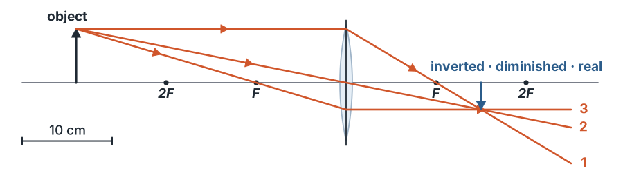
You do not need a bench to find an image: you can draw it. Every point of the object sends out light in all directions, and every ray from the tip of the arrow that passes through the lens arrives at the tip of the image. So any two rays from the tip are enough to find it, and three of them are easy to draw, because you know where they go.
- A ray parallel to the principal axis is refracted through the principal focus on the far side.
- A ray through the centre of the lens goes straight on, without changing direction.
- A ray through the principal focus on the near side is refracted parallel to the principal axis.
Where the rays cross is the tip of the image. The foot of the object is on the principal axis, so the foot of the image is on the axis too, directly above or below the tip.
To draw a ray diagram to scale, choose a scale that fits your paper, such as 1 cm on the paper for 5 cm on the bench. Draw the principal axis and the lens, and mark F on both sides. Draw the object as an arrow standing on the axis. Draw ray 1 and ray 2 from its tip with a sharp pencil and a ruler, and ray 3 as a check. Then measure the image distance and the image height on the paper and change them back with the scale.
 (enlarge)
Trap: “Only the two or three rays in the diagram make the image.” All the rays from the tip that pass through the lens meet at the tip of the image; the diagram shows only the rays that are easy to draw. Cover half of the lens, and the whole image is still there, only dimmer.
Worked example
A ray diagram to scale
An object 1.5 cm tall stands on the principal axis 6.0 cm from a converging lens of focal length 4.0 cm. Draw a full-size ray diagram and use it to find where the image is, how tall it is and what it is like.
Draw the principal axis and the lens, and mark F 4.0 cm from the lens on each side. Draw the object 6.0 cm from the lens, 1.5 cm tall. From its tip, draw ray 1 parallel to the axis to the lens, then on through F on the far side. Draw ray 2 from the tip straight through the centre of the lens. The two rays cross 12.0 cm from the lens on the far side, 3.0 cm below the axis. Ray 3, through the near F and then parallel to the axis, passes through the same point. The image is 12 cm from the lens on the far side, 3.0 cm tall: inverted, enlarged (twice the height of the object) and real.
Describing an image
An image is described with three pairs of words.
- Enlarged, same size or diminished: taller than the object, the same height, or shorter.
- Upright or inverted: the same way up as the object, or upside down.
- Real or virtual: a real image is formed where rays of light actually meet, so it can be caught on a screen placed there. A virtual image is formed where rays only seem to come from: no light passes through it, so it cannot be caught on a screen, and you see it only by looking into the lens or mirror. The image in a plane mirror is virtual. The next part is about virtual images made by lenses.
Your results fit one pattern, which you can check with a ray diagram for any lens, with distances measured in focal lengths:
| Where the object is | Where the image is (other side of the lens) | The image is |
|---|---|---|
| further than 2f | between f and 2f | real, inverted, diminished |
| at 2f | at 2f | real, inverted, same size |
| between f and 2f | further than 2f | real, inverted, enlarged |
| at f | no image: the rays leave parallel | — |
| nearer than f | on the same side as the object (next part) | virtual, upright, enlarged |
Trap: “A real image is one you can see, and a virtual image is an imaginary one that is not there.” You can see both kinds. The difference is whether the light really passes through the image: if it does, a screen there catches it.
Worked example
Describing images
A converging lens has a focal length of 5.0 cm. Describe the image of an object placed (a) 25 cm, (b) 10 cm and (c) 7.0 cm from the lens.
Twice the focal length is 2f = 10 cm. (a) The object is further than 2f, so the image is real, inverted and diminished, between 5 cm and 10 cm from the lens on the other side. (b) The object is at 2f, so the image is real, inverted and the same size, 10 cm from the lens on the other side. (c) The object is between f and 2f, so the image is real, inverted and enlarged, further than 10 cm from the lens. All three are real and inverted; the closer the object, the further away and bigger the image.
Free play: nothing here is marked or saved
The water-glass flip
A glass of water 8 cm across is a converging lens with a focal length f of about 8 cm, measured from its middle. Slide the card back, away from the glass, and watch the arrow seen through the water. When does it turn round, and when is it bigger than the arrow above?
Try: Slide the card back slowly. Where does the arrow in the water turn round?
- Card distance
- 4 cm
- Width in the water
- × 2
- It points
- the same way
Card 4 cm = 0.5 × f: nearer than f
Image: virtual, upright and enlarged: a magnifying glassSupplement
- Supplement Nearer than f the water is a magnifying glass: the arrow is upright and enlarged, a virtual image (part 2).
- At f there is no image: the arrow is smeared right across the glass.
- Beyond f the image is real and inverted: enlarged up to 2f, the same size at 2f, diminished further back.
- A glass curves one way only, so it reverses the arrow left to right but not up and down. A lens curved both ways turns the image upside down as well.
About this model. The water is treated as a thin converging lens with its centre in the middle of the glass. A glass 8 cm across, full of water, has a focal length of about 8 cm measured from its middle. You look from across the room, so the arrow in the water looks about as many times as wide as the image the glass forms; within 2 cm of f the width you see differs more from this number, so the numbers there say “about”. The glass walls are ignored, and a real glass also blurs the arrow near F and bends its edges more.
Case closed
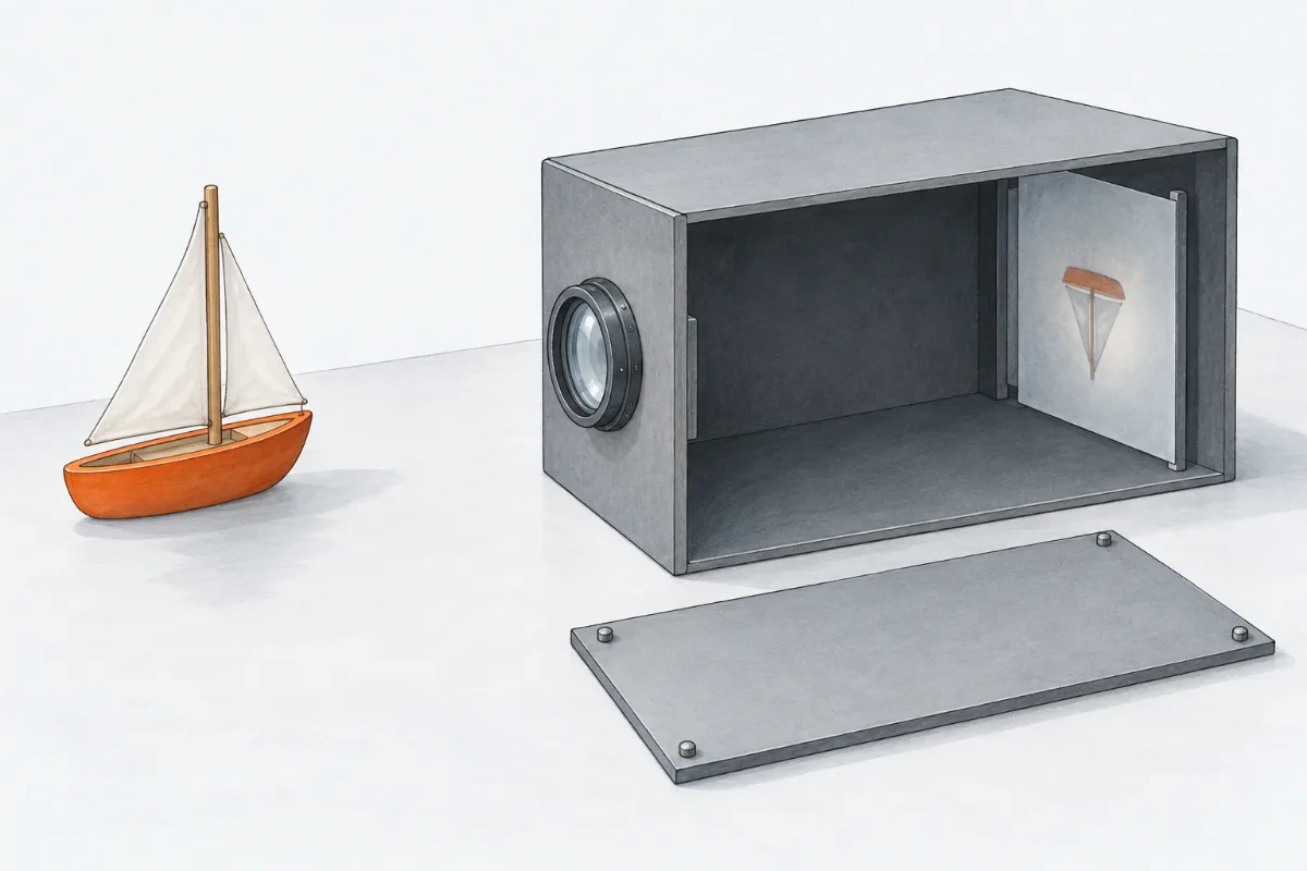
Back to the projector and the camera. A camera’s lens forms a real image of a scene that is much further away than twice its focal length, so the image is small, inverted and close to the principal focus, where the camera’s sensor is. In an old box camera, the image falls on a frosted glass screen at the back. Focusing means moving the lens until the sensor is exactly where the image is sharp, and a nearer subject needs the lens a little further from the sensor. A projector works the other way round. The slide sits just further from the lens than its principal focus, between f and 2f, so the image is enlarged and far away, on the screen across the room. It is also inverted, so the slide goes into the projector upside down, and the tree on the screen stands the right way up. Move the screen, and you have to refocus, because the image is sharp at only one distance.
 (enlarge)
About this model
The bench, the window, the lamp, the lens and the screen are simulated. The lens is a thin lens of focal length 10.0 cm and 5.0 cm across. The model puts each sharp image where a ray diagram drawn exactly would put it. It uses the lens equation, 1/f = 1/u + 1/v, where u is the object distance and v the image distance; you do not need the equation, because a careful ray diagram gives the same answers. The screen moves in steps of 1 cm, and the blurred patch is drawn as wide as the cone of light where the screen cuts it. A real lens is not a perfect thin lens: rays through its edges are brought together a little nearer the lens than rays through its middle, and different colours are focused at slightly different distances, so a real image is never perfectly sharp, and focal lengths measured on a real bench vary by a few millimetres.